Closed Loop Fluxgate Magnetometers
 Closed loop magnetometers operate in a 'null-field' mode. A feedback loop is used to apply just the right amount of current or voltage to the feedback winding to exactly null out the field component along the axis being measured. The amount of current or voltage feedback required to exactly null out the field, gives a measure of the field present.
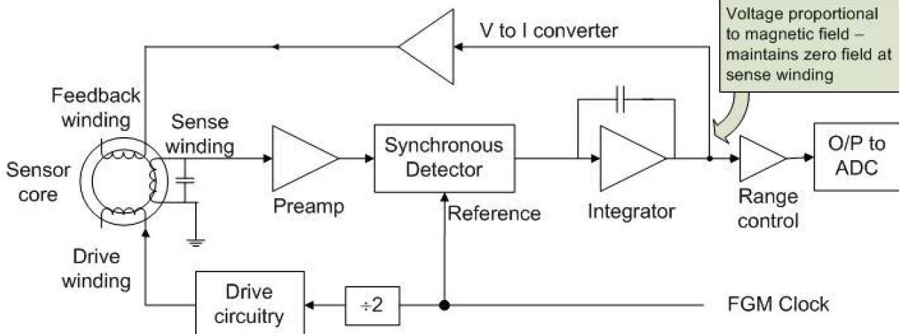
The block diagram below, shows the basic components of the analogue closed loop, current feedback, fluxgate magnetometer design used on the Double Star spacecraft. For clarity, a separate feedback winding is shown, however in the DoubleStar design, to save mass, the current is fed back directly into the sense winding.
-
As with the open loop design, the magnetometer is driven with a square wave (typically of the order of 10kHz) through the drive winding, the small, field proportional voltage induced in the sense winding due to the presence of a magnetic field is amplified by tuning the sense winding, and passing the signal through a pre-amplifier. The sign and magnitude of the measured field is then determined as a dc voltage level by the synchronous detector.
-
In the closed loop design, this voltage is fed to an integrator; because feedback is employed, the output of the integrator builds up until the current output from the voltage to current converter, when fed back through the feedback winding, creates a dc magnetic field in the sensor core which exactly cancels out the external field. At this stage, the field detected by the sense winding will be zero. The input to the integrator will be zero and the output of the integrator will be a DC voltage proportional to the magnetic field.
-
This voltage level is fed to the ADC via a set of range control amplifiers. The range control design depends on the range of fields the magnetometer is designed to measure, the resolution required and the size (number of bits) of the ADC. For example, for the DoubleStar magnetometer, there are 5 ranges, and an ADC of 14 bits. The measurement range and resolution of the magnetometer in each of these 5 ranges is shown in the table below.
Range Control: DoubleStar Magnetometer Range Amplification Measurement Range Resolution 7 x 1 +/- 32768nT 4nT 6 x 4 +/- 8192nT 1nT 5 x 16 +/- 2048nT 250pT 4 x 64 +/- 512nT 63pT 3 x 256 +/- 128nT 16pT Range Control: DoubleStar Magnetometer