X-Ray to MR: The Progress of Flexible Instruments for Endovascular Navigation
Hamlyn researchers provided a systematic review of the flexible instruments for endovascular navigation, aiming to aid X-Ray & MRI treatment for CVDs.
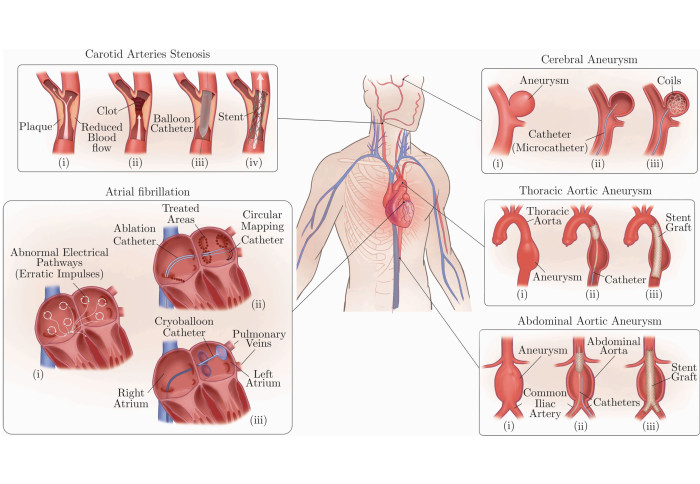
Cardiovascular diseases (CVDs) are disorders and diseases affecting the heart or blood vessels, which lead to heart attacks, strokes, critical leg ischemia, and account for one-third of all deaths in the world (17.9 million annually).

Endovascular interventions have become the backbone of treatment for CVDs (especially utilising in X-Ray and magnetic resonance imaging (MRI) treatments), thanks to its minimally invasive nature and its effectiveness in reducing hospitalisation and total time to recovery when compared to open surgery.
The minimally invasive and image-guided procedures of endovascular interventions are carried out by manipulating thin, long, and relatively flexible instruments (sheaths, catheters, and guide-wires) within the vasculature to gain access to specific blood vessels, commonly referred to as catheterisation.
X-Ray to MRI
Although X-Ray fluoroscopy is currently the gold standard imaging technique for endovascular interventions, it presents occupational safety hazards to medical personnel and potential risks to patients, especially paediatric patients, because of its inherent ionising radiation.
On the other hand, MRI (with its unique ability to provide radiation-free imaging, and acquiring morphologic and functional information) holds great promise in the advancement of image-guided navigation through the vasculature. Moreover, MRI has the potential to combine diagnosis, therapy and early evaluation of therapy in the same intervention.
However, MR-guided interventions also face a major challenge due to the presence of a large magnetic field (1.5/3 Tesla), which limits the set of materials suitable for the construction of key instrumentation (sheaths, catheters and guide-wires). Yet, significant progress has been made in the development of interventional devices, which comprise biocompatible, MR safe and MR visible materials.

The Progress of Flexible Instruments for Endovascular Navigation - A Systematic and Illustrated Review
In view of this, our researchers at the Hamlyn Centre provided a systematic and illustrated review regarding the progress of flexible instruments for endovascular navigation, aiming to encourage and accelerate the development of MR-guided endovascular instrumentation, as well as assist X-Ray & MRI treatments for CVDs.
This systematic review covered three main categories (keywords for literature up-to-date search [until October 2020 inclusive] are listed in brackets): (a) instrument (MR/MRI/magnetic resonance (imaging), guide∗, guide-wire, steer∗, deflect∗, selective), (b) medical region (card∗, heart∗, atri∗, vasc∗), (c) instrument tracking (MR/MRI/magnetic resonance (imaging), device tracking, catheter tracking, visualisation).
In this review, our researchers
- first introduced commercial guide-wires and selective catheters, as well as the current state-of-the-art devices used for navigational purposes in endovascular interventions;
- presented the strengths and limitations of these instruments in terms of navigation in the human vasculature and their accompanied side effects (mainly increased exposure to ionising radiation);
- reviewed commonly proposed techniques (i.e., steerable catheters and robotic platforms) to overcome the navigational challenges and limitations of performing interventions under X-Ray fluoroscopy guidance;
- subsequently presented a commonly proposed and investigated route, i.e. adopting MRI as an alternative imaging modality for its unique strength and capabilities when compared to X-Ray fluoroscopy;
- briefly went through the fundamental physics of MRI, followed by showcasing the ongoing efforts made by academia and industry to develop instruments compatible for use in MR environments through the adoption of different materials and manufacturing methods;
- outlined MRI's huge potential in combining diagnosis, therapy and early evaluation of therapy in the same intervention; and
- used this systematic review as a base for defining the future requirements and challenges of developing MR safe and visible instrumentation for endovascular interventions.
![Guide-wire Classification: [LEFT] (a) Two different types of commonly used guidewire tips (distal ends): curved (angled) and straight. The distal ends tend to be heat treated to set the desired shape, e.g.‘J’-shape. (b) The transition from an untapered to a tapered core wire using centreless grinding to achieve the desired taper profile across the distal end in (c). For (c)–(g), a sectioned view of the distal end of commercially available guidewires and their corresponding insets, illustrating the core design and its surrounding elements (coils, ribbons, etc). (c) Guidewire widely used in peripheral interventions (Radifocus Guidewire (Terumo Europe NV, Leuven Belgium)). This type has a core-to-tip design and is fully covered with polymer. For radiopacity, the tip is plated with a radiopaque material (gold in this illustration). (d)–(g) Guidewires comprising a radiopaque coil instead of the aforementioned radiopaque plated core tip. Classification based on polymer covering: (d) and (e) guidewires covered fully with polymer, and (f) and (g) guidewires partially covered with polymer. Classification based on core design: (d) and (f) core-to-tip design, and (e) and (g) shaping/forming ribbon design. Guidewire coating: (b) has an additional layer of hydrophilic polymer that is added to improve lubricity, trackability and manoeuvrability. On the other hand, (e) employs a hybrid approach by coating the distal-most point with a hydrophobic polymer (e.g. silicone) to enhance tactile feedback and tip control. Note: The illustrated examples are merely a few examples of commercially available coating configurations. | [RIGHT] (a)–(h) Guidewires comprising a radiopaque coil and an additional support coil to promote the tip’s resilience and mechanical properties. A sectioned view of the distal end of commercially available guidewires and their corresponding insets, illustrating the core design and its surrounding elements (coils, shaping ribbon). Classification based on support coil placement: (a)–(d) coaxially placed support coil (commonly stainless steel) with respect to a radiopaque coil, and (e)–(h) support coil placed in series with respect to a radiopaque coil. Classification based on polymer covering: (a), (b), (e) and (f) guidewires fully covered with polymer, and (c), (d), (g) and (h) guidewires partially covered with polymer. Classification based on core design: (a, c, e and (g) core-to-tip design, and (b), (d), (f) and (h) shaping/forming ribbon design. Guidewire coating: (b), (c) and (f) have an additional layer of hydrophilic polymer to improve the guidewires’ lubricity, trackability and manoeuvrability. Conversely (g) employs a hybrid approach by applying a hydrophobic polymer (e.g. silicone) at the distal-most point to enhance tactile feedback and tip control. Note: The illustrated examples are merely a few examples of commercially available coating configurations.](/newsarchive/images/mainnews2012/guidewire-classification_1628184096757_x2.jpg?r=4982)
Guide-wire Classification: [LEFT] (a) Two different types of commonly used guidewire tips (distal ends): curved (angled) and straight. The distal ends tend to be heat treated to set the desired shape, e.g.‘J’-shape. (b) The transition from an untapered to a tapered core wire using centreless grinding to achieve the desired taper profile across the distal end in (c). For (c)–(g), a sectioned view of the distal end of commercially available guidewires and their corresponding insets, illustrating the core design and its surrounding elements (coils, ribbons, etc). (c) Guidewire widely used in peripheral interventions (Radifocus Guidewire (Terumo Europe NV, Leuven Belgium)). This type has a core-to-tip design and is fully covered with polymer. For radiopacity, the tip is plated with a radiopaque material (gold in this illustration). (d)–(g) Guidewires comprising a radiopaque coil instead of the aforementioned radiopaque plated core tip. Classification based on polymer covering: (d) and (e) guidewires covered fully with polymer, and (f) and (g) guidewires partially covered with polymer. Classification based on core design: (d) and (f) core-to-tip design, and (e) and (g) shaping/forming ribbon design. Guidewire coating: (b) has an additional layer of hydrophilic polymer that is added to improve lubricity, trackability and manoeuvrability. On the other hand, (e) employs a hybrid approach by coating the distal-most point with a hydrophobic polymer (e.g. silicone) to enhance tactile feedback and tip control. Note: The illustrated examples are merely a few examples of commercially available coating configurations. | [RIGHT] (a)–(h) Guidewires comprising a radiopaque coil and an additional support coil to promote the tip’s resilience and mechanical properties. A sectioned view of the distal end of commercially available guidewires and their corresponding insets, illustrating the core design and its surrounding elements (coils, shaping ribbon). Classification based on support coil placement: (a)–(d) coaxially placed support coil (commonly stainless steel) with respect to a radiopaque coil, and (e)–(h) support coil placed in series with respect to a radiopaque coil. Classification based on polymer covering: (a), (b), (e) and (f) guidewires fully covered with polymer, and (c), (d), (g) and (h) guidewires partially covered with polymer. Classification based on core design: (a, c, e and (g) core-to-tip design, and (b), (d), (f) and (h) shaping/forming ribbon design. Guidewire coating: (b), (c) and (f) have an additional layer of hydrophilic polymer to improve the guidewires’ lubricity, trackability and manoeuvrability. Conversely (g) employs a hybrid approach by applying a hydrophobic polymer (e.g. silicone) at the distal-most point to enhance tactile feedback and tip control. Note: The illustrated examples are merely a few examples of commercially available coating configurations.

Guidewire-Classification: (a) A sectioned view of the distal end of a guidewire comprising a nitinol hypotube coaxially placed with respect to a radiopaque coil. The insets illustrate the core design and its surrounding elements (hypotube, core, coil). The design shown falls under the core-to-tip design category and consists of a partial polymer covering. Although not illustrated, the distal end can also be coated with hydrophilic/hydrophobic coatings to achieve the desired mechanical and physical properties. (b) Spring-coil covered guidewire with a fixed core design. (c), (d) Spring-coil covered guidewire with a movable core design. (c) Initial state of the guide wire, i.e. angled distal end (tip). (d) The proximal end is pushed, thereby moving the core wire with respect to the spring coil, which in turn straightens the distal end (tip). The safety wire in (b)–(d), illustrated in red, minimises the possibility of tip detachment if the spring coil breaks. | Catheter Guide-wire Fluoroscopy Example: 2D x-ray fluoroscopy sequence illustrating the catheterisation of the left renal artery (LRA) in an abdominal phantom (Elastrat, Geneva, Switzerland) using a selective catheter, IMPRESS, size = 5 F (1.667 mm outer diameter), distal end shape: head-hunter 1, length = 100 cm, inner diameter = 0.046 ′ ′ (1.17 mm), Reference: 510035HH1 (Merit Medical OEM, UT, US) and a guidewire, Radifocus Guide-wire M Standard Type Guide-wire, length = 180 cm, Outer Diameter = 0.035 ′ ′, flexible length = 10 mm, Angled Distal Tip, Reference: RF-GA35181M, (Terumo Europe NV, Leuven Belgium). (1) Indicates the LRA target and the catheter. (2) Guidewire is advanced over the LRA whilst keeping the catheter in place. The catheter’s distal end straightens due to the advancement of the guidewire. (3) Catheter is advanced over the guidewire. (4) Guidewire is partially retracted and the catheter restores the pre-shaped distal end. (5) The catheter is rotated to adjust its orientation. (6)–(8) The catheter and guide-wire assembly is slowly retracted towards the LRA. (9) The catheter’s distal end slides into the LRA, (10)–(11) The guide-wire is advanced through the catheter to prevent the catheter from flipping back to the abdominal aorta. (12) The catheter is advanced over the guidewire.

Guiding catheter fabrication steps: (a) a ram extruded PTFE mandrel is fed through a chemically etched ram extruded PTFE liner to prevent the liner from collapsing during the subsequent processes. (b) The liner/mandrel assembly is then braided with stainless-steel wires (e.g. 50 μm 316 L stainless-steel round wires) using a maypole braiding machine. (c) A small section of the liner is left non-braided to create a flexible atraumatic tip. (d) A multi-durometer PEBAX outer layer is applied on top of the braided liner/mandrel assembly to encapsulate the braid. The stiffness of the outer catheter decreases progressively from the proximal end (Shore Hardness 72D) to the distal atraumatic radiopaque tip (Shore Hardness 35D). The transition segments (45D and 55D) are added to reduce the possibility of catheter kinking caused by abrupt changes in flexibility. This fabrication step can be achieved using various techniques, including thermal bonding of multi-durometer segments [25], intermittent extrusion [26]. (e) The PTFE mandrel is pulled out of the laminated tube. (f)–(g) The laminate is mounted onto a forming wire to form the desired distal end shape. (h) The distal end shape is modified using a template (e.g. Judkins right 4) and placed in a forming oven for a predetermined temperature and time. (i) After annealing, the assembly is cooled, followed by the removal of the forming wire.

MR Physics (I): (a) A human tissue voxel largely made of water and fat, which contain hydrogen atoms. (b) A simplified representation of the nucleus of a hydrogen atom. The nucleus is a positively charged proton with an intrinsic property, called spin or intrinsic angular momentum. The non-zero net spin generates a magnetic dipole moment (μ or MDM for short), which in turn generates a small magnetic field. MDMs and spins are used interchangeably in literature because they track each other. (c) A further simplified representation of the nucleus, which is used in the rest of the figure. (d) In the absence of an external magnetic field, the atoms’ MDMs are pointing randomly, hence giving a uniform distribution of MDMs in the top and isometric views of an implicit coordinate system. The net magnetisation (denoted by M) is the sum of the individual MDMs. In the absence of an external magnetic field, M is zero. (e) Upon the application of an external strong static magnetic field (B0 ), i.e. the patient is placed in the MRI bore, two events take place: (1) The orientation of the MDMs is skewed slightly toward B0 ’s direction (increased density of MDMs) resulting in an increase in M (yellow arrow), (2) The ensemble of MDMs start processing at the Larmor frequency (42 MHz at 1 Tesla) around B0 ’s direction. Although the spins are processing, M remains in equilibrium.

MR Physics (Il): (a) RF Pulse Excitation: When a rotating homogeneous RF field, denoted by B1, is applied perpendicular to B0, the entire magnetisation distribution, is tipped away from its initial alignment with B0 (90? in this example). Simultaneously, the magnetisation distribution slowly rotates around the rotating B1 axis (indicated by the blue circular arrow). Notes: the path followed by M is observed from a stationary frame of reference, B1 field does not change the relative orientation of individual MDMs, and the B1 field rotates at the Larmor frequency. (b) After switching off the rotating RF field, M returns to thermal equilibrium (relaxation), i.e. aligning back to B0 direction. The inset (c) is zoomed-in in (d). (d) Plot illustrating the two magnetisation components of M, and their corresponding relaxation times. T2 is the time required for the transverse magnetisation (Mxy) to decrease exponentially to approximately 37% (1/e) of its initial value. Conversely, T1 is the time required for the longitudinal magnetisation (Mz) to return to 63% (1−1/e) of its maximum value (M0), where M is equal to M0 at equilibrium (i.e. aligned with B0 ’s direction). Mxy is the component detected by the RF receiving coils which gives rise to the MR image. Mz does not contribute to the acquired signals. An important mechanism for the decay in Mxy, i.e. T2 relaxation (spin-spin relaxation) is as follows. The MDMs (spins) experience local fields which are combinations of B0 and the fields from their neighbouring protons’ MDMs. The variations in local fields lead to different local precessional frequencies, and as a result, the protons’ MDMs (spins) fan out in time, thereby reducing Mxy. The fanning out of MDMs (spins) is referred to as dephasing. T1 relaxation (spin-lattice relaxation), on the other hand, occurs when a proton exchanges magnetic energy with its external environment (lattice). T1 relaxation also results in T2 relaxation, ensuring that T2 is longer than or equal to T1. Note: The transition in (b) illustrates the overall effect of both relaxation mechanisms.

MR Guidewires (I): (a) Guidewire consisting of a glass-fibre reinforced PEEK core covered with a polyurethane jacket. The core is grounded at its distal end to create a flexible distal end. (b) Cross-sectional (inset) of the micro-pultruded glass-fibre reinforce PEEK core. (c) Guidewire comprising a PEEK core with iron microparticles embedded in the polymeric coating. (d) Steerable guidewire composed of a flexible PEEK shaft, a deflectable tip and a Dyneema tendon travelling through the entire guidewire. The steerable tip is a re-purposed 2.4Fr microcatheter (flexible tube) embedded with a flattened nitinol rod to straighten the tip and to constrain its bending in one direction. At the very distal end of the guidewire is a PEEK cap. The entire body is covered with polyethylene heat shrink tubing to hold all the components together. (e) Pulling of the tendon results in the bending of the deflectable tip. (f) Guidewire constructed using short nitinol rod segments (guidewire shaft) and a tapered nitinol rod with a long coil mounted onto it (flexible distal end). The distal end is jacketed with a non-braided thermoplastic polymer and the entire body is covered with a soft polymer. (g)–(h) Zoom-in cross-sectional (inset) of the guidewire shaft which consists of nitinol rod segments (grey) joined by nitinol connectors (blue) with notched ends. For electrical insulation, the nitinol rod is coated with a thin film of parylene and jacketed with PEBAX to achieve a consistent profile (between rods and connectors). ∗MRI markers are passive (−ve).

MR Guidewires (II): (a) Stiff MaRVis guidewire comprising of a shaft and an iron-doped PEBAX flexible distal end. (b) Cross-sectional zoom-in (inset) of the shaft that consists of micropultruded glass or aramid fibres embedded in epoxy resin and in certain cases iron-doped epoxy resin for MR visibility (referred to as MaRVis rods). To construct the guidewire shaft, several MaRVis rods are arranged and embedded in a polymer matrix and are subsequently covered with a PTFE heat shrink tubing. (c) Further zoom-in (inset) of a MaRVis rod. (d) Further zoom-in (inset) of an iron-doped MaRVis rod. (e) Guidewire consisting of twisted high strength synthetic aramid fibres, surrounded by rings of passive negative markers for MR visibility (placed at discrete points) and a polymer composite to provide the desired mechanical performance. At the distal end, a flexible radiopaque tip is mounted at the tip for enhanced tip visibility. The entire body is covered with a PTFE heat shrink tubing. In Wolska-Krawczyk et al, instead of the coil and PTFE layer, the tip section was coated with PEBAX and the guidewire was coated with a hydrophilic polymer. (f)–(g) Guidewire comprising a micropultruded glass-fibre reinforced core wrapped and consolidated with additional layers of high strength synthetic fibres. Passive negative markers are applied at discrete intervals for MR visibility and an outer layer is utilised to form the guidewire. (h) Flexible tip achieved by small winding pitch and (i) High bending and torsional stiffness of guidewire shaft achieved by large winding pitch.

(Manual) Tendon Driven Catheters for MR-guided interventions (I). (a) A uni-directional catheter inspired by Bell et al’s design: The deflectable distal end consists of a nitinol laser-cut hypotube, connected to a Kevlar tendon. In the case of Bell et al, a nitinol spring was concentrically added to the laser profiled tube. (b) Yao et al’s uni-directional steerable catheter: A nitinol supported PTFE tube was used as the deflectable distal end. A control wire glued to a control rod was used for steering. (c) Clogenson et al’s multi-selective catheter: The design comprises a laser profiled PEEK tube with four tendons travelling through the entire catheter length. The first pair of tendons control segment#1 and the second pair of tendons control segment#2. In terms of joint design, a sliding curved joint was utilised to form the articulated deflectable segments. Note: The catheter is made from a single material, however, different segment colours (red and beige) are used only used for illustrative purposes.

(Robotic) Tendon Driven Catheters for MR-guided interventions (II). (a) Simplest form of concentric or telescopic catheters: the system consists of two uni-directional catheters (inner leader catheter and outer guide catheter) which are controlled independently and collaboratively to recreate the shapes of common selective catheters. (b) Ataollahi et al’s additively manufactured deflectable catheter: The design consists of clockwise and counter-clockwise helical segments employed in an alternating fashion (illustrated in yellow and white). To control the distal end in 3D space, four polymeric tendons were utilised.

Distal end of Hydraulic Driven Catheters (HDCs): (a) Haga et al’s uni-directional HDC: A laser profiled nitinol tube covered with a thin silicone rubber tube is controlled by changing the negative pressure of the fluid. (b) De Boer et al’s conceptual design of a multi-directional HDC: the distal end comprises a central lumen and four parallel pressurisable chambers. Changing the inner fluid pressure results in the bending of the deflectable tip of the catheter. Note: The figure illustrates deflection in only two directions. (c) Skerven et al’s conceptual design of a multi-directional (External Balloon) HDC: the deflectable tip consists of four external balloons attached to a flexible tubing. To steer the distal end towards a specific direction, the external balloons are inflated (pressurised) and deflated (unpressurised) accordingly. Similar to De Boer et al’s design, the figure illustrates deflection in only two directions. (d) Johansen et al’s conceptual design of an (Internal Balloon) HDC: The distal end includes a corrugated section attached to the inner tube and an asymmetric internal balloon attached to the outer tube. The internal balloon is configured to deflect the distal end of the catheter. (e) Ikuta et al’s single-input, multi-output HDC: The steerable tip consists of serially placed, independently valve-controlled bellows. To bend a specific segment, the target valve is opened by increasing the pressure of the driving tube until it reaches the activation pressure band of the valve. The figure illustrates the case where both segments (bellows) are actuated.

Distal end of MR-actuated Magnetic Catheters (a) (Simplified, Single Plane) microcoil-based: a microcoil is attached to a flexible tubing. Depending on the direction of flow of current, the distal bend is steered in a specific direction accordingly. (b) Ferromagnetic sphere-based: The deflectable tip consists of ferromagnetic spheres. (c) Ferrofluid-based: The distal end comprises a balloon filled with a ferrofluid. All three distal ends (a)–(c) experience a turning force or torque to align its local magnetic field with the external field of the MRI scanner. The distal ends in the figure are placed within the bore of the MRI scanner, indicated by the three main components: main magnetic coil, gradient coils and RF Coils.

Distal end of shape memory alloys (SMAs) actuated catheters: (a) SMA Microcoils/Springs (Fu et al’s design): this design comprises three microcoil actuators, a bias spring and links (to fix and integrate the SMA actuators and bias spring). A silicone tube was utilised to cover the entire configuration. (b) Electrochemically etched SMA sheets (Mineta et al’s design): an SMA sheet was electrochemically etched into SMA (flat-spring-like) actuators, which were then attached to a helical bias spring. To form a unitary body, an outer tubing was employed, and inner tubing was added to facilitate the insertion/removal of guidewires and intravascular devices. Namazu et al utilises similar fabrication and actuation techniques. (c) SMA wires: In this design, a plurality of parallel SMA wires (three or four) are embedded into a flexible multi-lumen tube. In all three embodiments of SMA actuated catheters (a)–(c), the actuators are embedded/added in an elongated (pre-loaded) condition and are distributed at an angle of 120?. When the SMA actuator(s) is heated (illustrated in red), it contracts and results in the bending of the distal end towards a specific direction. (d) Conceptual design of a laser-profiled SMA tube (Langelaar et al’s design): the distal end consists of laser-cut (or etched) a small diameter SMA tubing. The laser cut patterns facilitate the bending of the distal end in two orthogonal directions. When a specific segment of the tube is locally heated, it contracts, and the distal end bends accordingly. In all the four cases illustrated (a)–(d), only two bending directions are shown (for better clarity).
Data Availability Statement: The 3D CAD models (Solid-works and STEP files) used in this article are openly available in the fig-share repository: please click Here.
This research was supported by EPSRC Programme Grant “Micro-robotics for Surgery (EP/P012779/1)” (Mohamed E M K Abdelaziz, Libaihe Tian, Mohamad Hamady, Guang-Zhong Yang and Burak Temelkuran, "X-ray to MR: the progress of flexible instruments for endovascular navigation", Progress in Biomedical Engineering, 3 (3), August 2021).
Article supporters
Article text (excluding photos or graphics) © Imperial College London.
Photos and graphics subject to third party copyright used with permission or © Imperial College London.
Reporter
Erh-Ya (Asa) Tsui
Enterprise