 TASR, the Transient Air System Rig, is a unique experimental facility that recreates both the transient and pulsating gas dynamics present in the air systems of internal combustion engines. This allows multistage air system performance to be ascertained under engine-realistic conditions, but without the need for expensive and time consuming engine testing. This page explains the background and motivation behind TASR, its main design features, capabilities and potential applications. For any further enquiries, please contact Dr Aaron Costall.
Downloads
TASR description
- Background
- Motivation
- Objectives
- Design
- Advantages
- Results
- Applications
- Conclusions
- Acknowledgements
- References
We are witnessing a period of great change in the automotive industry. Road transport in the EU accounts for around 20% of all emissions of CO2, the main greenhouse gas. The shift to hybrid/electric powertrains in passenger car and light-duty vehicles with ultra-low or zero CO2 tailpipe emissions continues, but a complete transition will take decades. This is especially so for heavy-duty applications, which are not well-suited to current electrical energy storage technology. In fact, between 1990 and 2010 CO2 emissions from heavy-duty vehicles actually grew by ~36% [1], due to expanding demand for road freight and stagnant fuel economy. Irrespective of the future powertrain technology mix across sectors, the internal combustion (IC) engine will remain the most numerous prime mover, and the consensus [2] is that we must continue to strive to raise the efficiency of thermal propulsion systems in order to reduce CO2 emissions across all modes of transport.
-
To measure performance of multi-stage engine air systems under engine-realistic conditions, but without an engine
-
To reproduce the unsteady gas dynamics in an IC engine exhaust manifold undergoing a specified transient event
To meet these objectives, TASR will need to be able to generate two timescales of unsteadiness:
-
Transient – timescale of engine acceleration, in the order of 100 Hz
-
Pulsating – timescale of exhaust pulses due to opening and closing of valves, order of 101–102 Hz
-
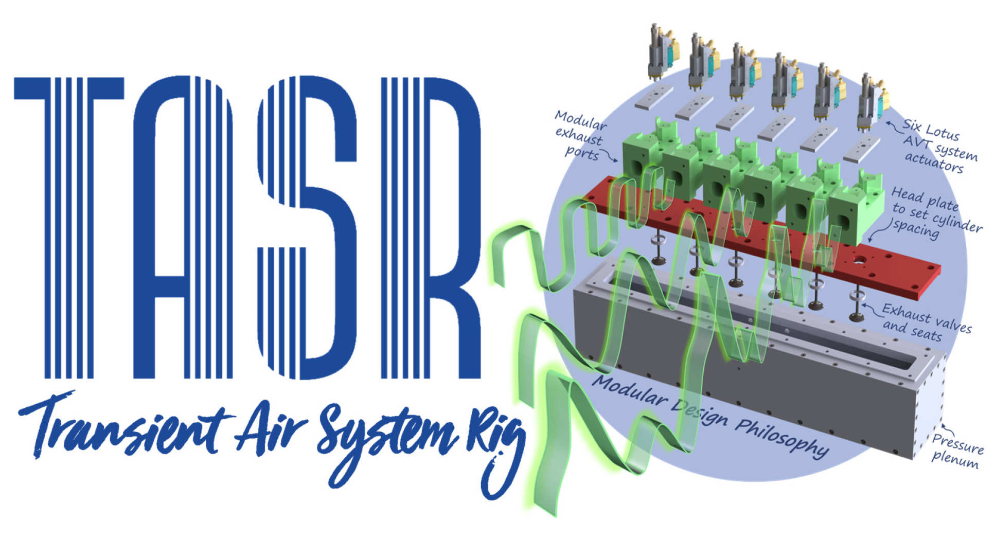
Transients are created by a fast-acting pressure regulating valve, which imposes ramps in the mean flow entering the pressure plenum (Figs 2 & 3), to imitate vehicle-level events
-
Pulses are generated by a Lotus AVT (Active Valve Train) system [3], comprising six electrohydraulic poppet valve actuators, with corresponding mounting plates, exhaust ports, valves and seats, which are installed on top of the pressure plenum (Fig. 2)
-
Our modular design philosophy allows different engine cylinder spacing to be accommodated with a minimum of part changes, while the simple plenum design can be adjusted for overall volume, or be adapted to include internal features
TASR offers numerous advantages over traditional gas stand or engine testing:
-
It isolates the air system from combustion effects and associated confounding factors
-
The non-combusting flow permits new manifold and turbocharger concepts to be inexpensively and rapidly 3D-printed in plastic, ready for immediate testing
-
Its capabilities (Tab. 1) and modular design, which is not restricted to any particular cylinder configuration, allows a wide range of engine air systems to be evaluated
Figure 4 (a) shows the rapid air system response to a step change in demanded plenum pressure. Figure 4 (b) shows the response of the high pressure stage in a 2-stage air system for a 7-litre industrial diesel engine, highlighting the out-of-phase pressure pulses entering either limb of the twin-entry turbine (inset).
-
Multistage air system matching under engine-realistic, transient-pulsating conditions
-
Unsteady 1D and 3D CFD (Fig. 5) model validation
-
Performance validation and optimization of new air system concepts and components, in steady-state, pulsating and transient-pulsating operation (Fig. 6)
-
Valve event optimization; effect of pulse frequency, amplitude and shape on air system performance
-
Intake and exhaust system acoustics
-
TASR, the new Transient Air System Rig, has been commissioned at Imperial College London
-
It simultaneously recreates transient and pulsating gas dynamics entering an engine air system
-
Engine air system performance can be measured in engine-realistic conditions, without recourse to expensive and time consuming engine testing!
The TASR was built as part of the High Performance Engine Air System project, which is a collaboration between Imperial, Caterpillar Inc., and Honeywell Transportation Systems. It was commissioned as part of the Energy Technologies Institute (ETI)’s Heavy Duty Vehicle Efficiency Programme [4].
-
European Commission (2014) Strategy for reducing Heavy-Duty Vehicles' fuel consumption and CO2 emissions. Communication from the Commission to the Council and The European Parliament, COM(2014) 285 final. Last accessed 17-06-2018. Retrieved from https://eur-lex.europa.eu/legal-content/EN/TXT/?uri=celex:52014DC0285
-
Automotive Council and Advanced Propulsion Centre (2017) Product Roadmap 2017: Commercial and Off-highway Vehicle. Last accessed 17-06-2018. Retrieved from https://www.automotivecouncil.co.uk/wp-content/uploads/sites/13/2017/09/CV_OH-Roadmap.jpg
-
Group Lotus plc. (unknown date) Active Valve Train. Last accessed 20-06-2018. Retrieved from: http://www.lotuscars.com/engineering/active-valve-train
-
Energy Technologies Institute (2018) Technology Programmes: Transport – HDV. Last accessed 20-06-2018. Retrieved from: http://www.eti.co.uk/programmes/transport-hdv