Capabilities & features
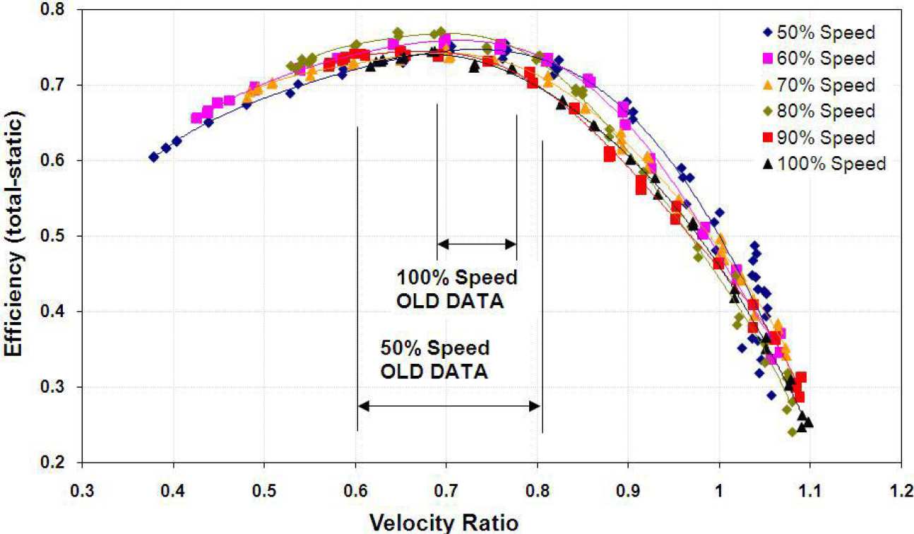
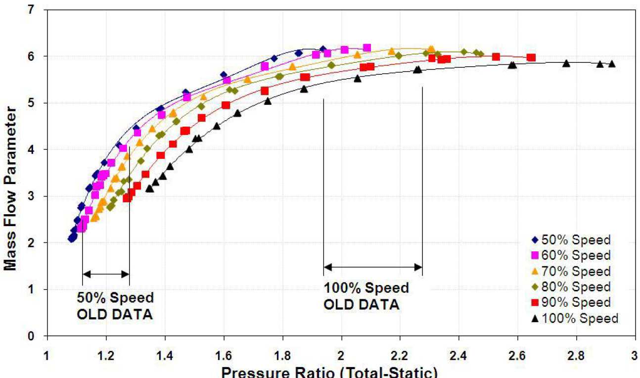
The test rig is equipped with an eddy current dynamometer which enables turbine testing within a large velocity ratio range. In comparison to traditional testing, where the turbine is loaded with a compressor, this allows a much wider range of variation in velocity ratio and pressure ratio, as shown on the graphs below ('OLD DATA' refers to the range of data typically available from a conventional test stand).
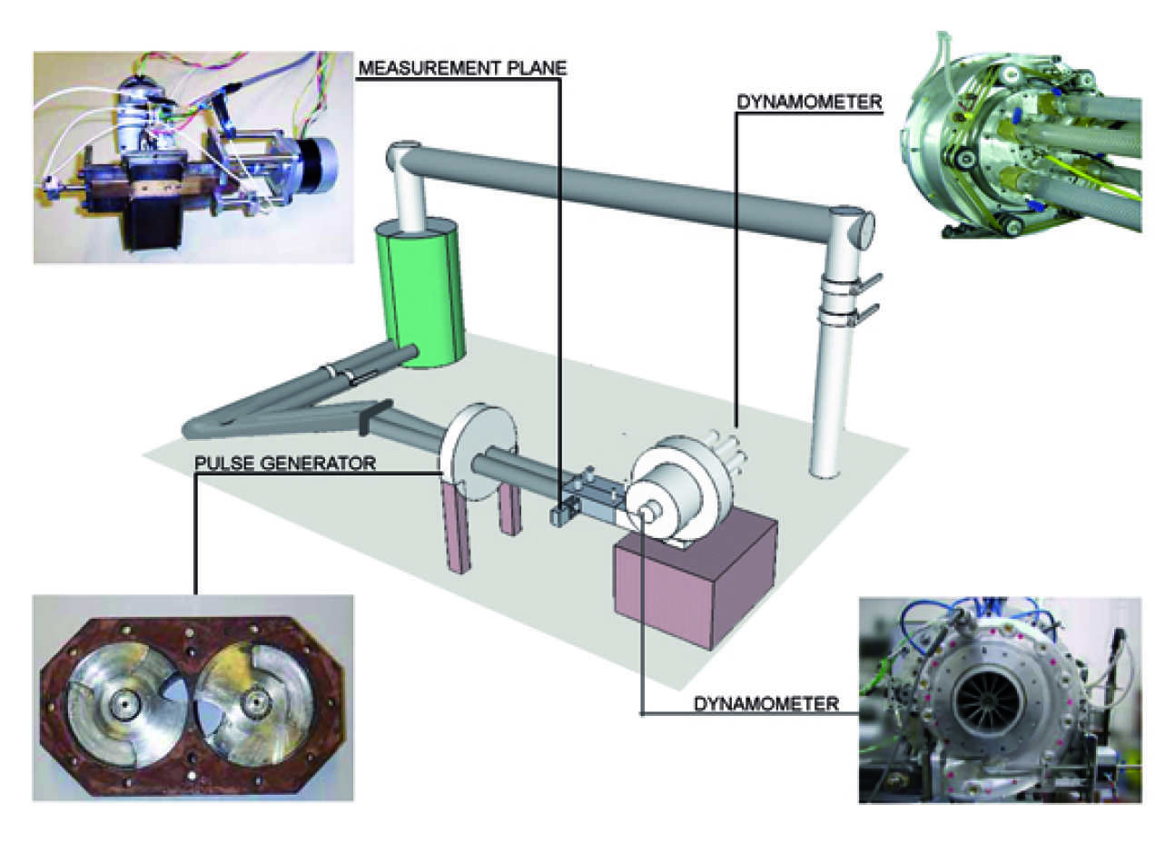
The test rig is supplied by screw-type compressors, capable of delivering air up to 1.2 kg/s mass flow rate at a maximum pressure of 5 bars (absolute). The two separated streams of air flow each pass through a rotary air pulse generator, which consists of two rotating chopper plates. The chopper plates consist of unique cut-outs designed at Imperial College to experimentally simulate the exhaust gas pulsation of an engine. A variable speed D.C. motor controls the rotating frequency of the chopper plates, hence the frequency of the pulsation. The phase of the entry pulses in both the limbs can be varied either to be in-phase or out-of-phase by changing the relative position of the two chopper plates. Downstream of the pulse generator the airflow is monitored at the 'measurement plane', an instrumented section containing static pressure tappings, fast response pressure transducers, thermocouples and a hotwire traversing system. After going through the measurement plane the air flows into the turbine stage where the torque is measured with the eddy-current dynamometer.
The dynamometer available at Imperial College is suited for testing of small and medium sized turbocharger turbines under steady and pulsating conditions.
The eddy-current dynamometer allows operation over a full range of speeds ranging from 0 - 60000 rpm. The dynamometer has a power absorption range of 1.7 - 62.2 KW at 60000 rpm and a low known inertia which allows the turbine to respond to pulsed flow, mimicking the behaviour of a standard assembly but with improved range.
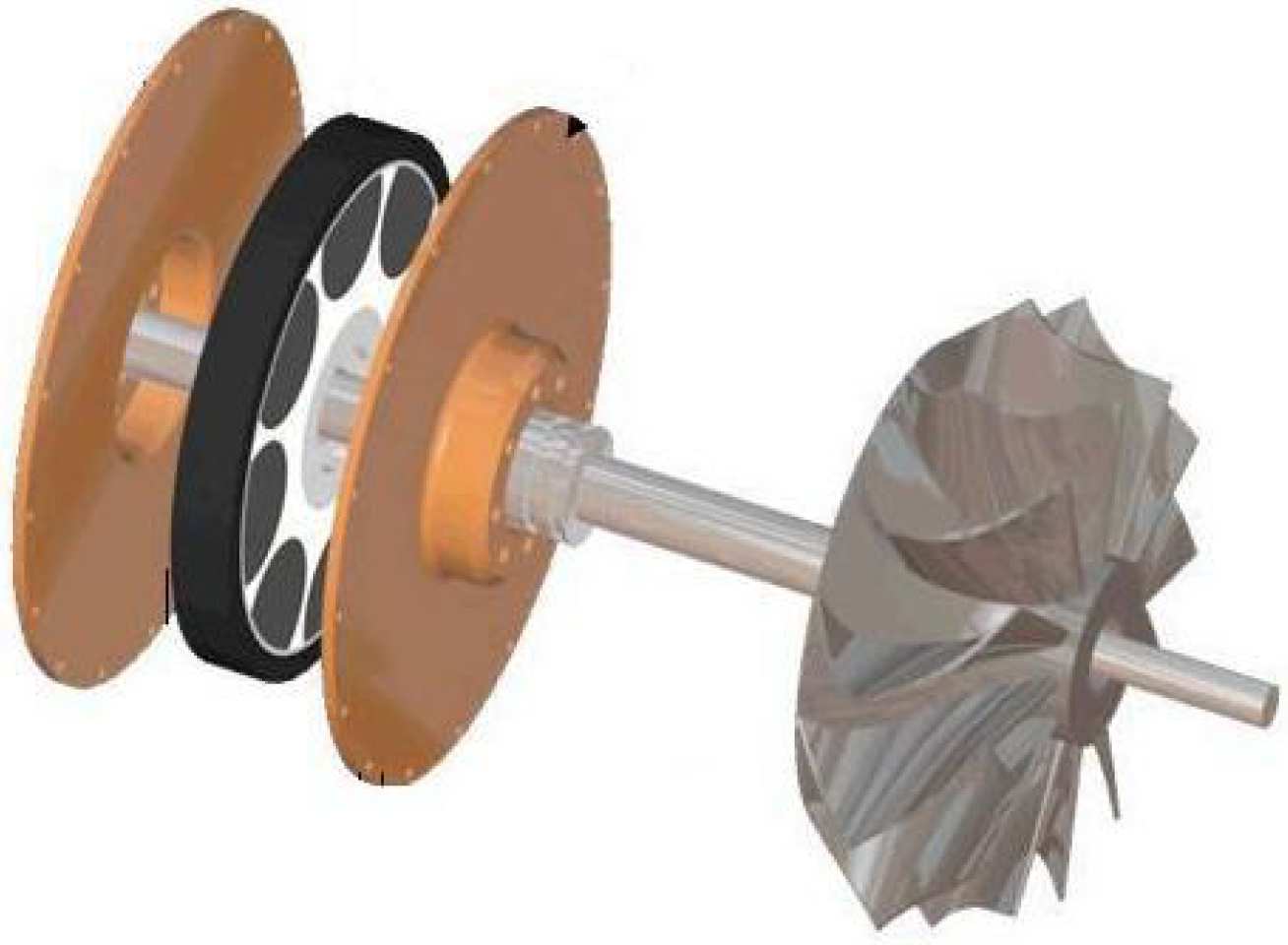
The dynamometer works on the principle of eddy-current braking by incorporating 14 magnets onto a rotor. This rotor spins co-axially between a set of stationary water-cooled conducting plates known as stators, which are located on either side of the rotor. The stators are connected to the main body of the dynamometer which is attached to a gimble bearing system held by a load cell coupling. The torque generated by the turbine is measured from the load cell reaction.
Dynamometer specifications
- Speed range: 0 - 60000 RPM
- Load range: 1.7 - 60+ kW
- Low inertia: ≥ 4.262x10⁻⁴ kgm2
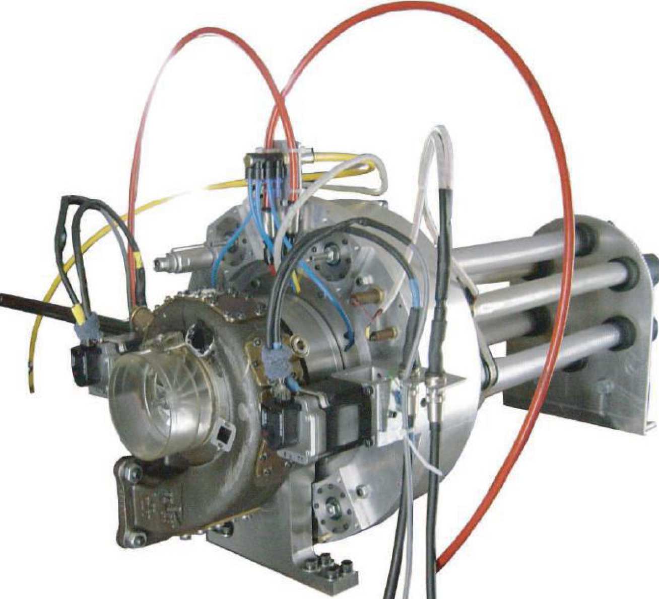

Caption: Front view of eddy current dynamometer with turbine and fast response pressure transducers installed around the volute periphery.

Caption: Rear view of eddy current dynamometer showing inlet and outlet cooling pipes and stepper motors for adjustment of gap (loading).