Video for electrical circuits activity
The Science
In this activity, you will explore simple electrical circuits and fundamental concepts of voltage and current.
Electrical circuits are organised in various possible combinations. The two basic arrangements are series (Figure 2) or parallel (Figure 3) connected circuits. The flow of current is described by Ohm’s law, which states the current passing through any conductor between two points is directly proportional to the voltage between the two points. The formula is as follows.
V = IR
Where V is voltage (volts), I is current (amps) and R is resistance (ohms)
The voltage, which comes from a power source (e.g. a battery or potato), serves as the driving force that pushes the electrons through a conductor. The larger the voltage, the more force is available to push the electrons. A suitable analogy to underscore the concept of voltage and current is that of water flowing through a pipe. In Figure 1, we assume there is water in the pipe flowing from A to B. In (1), the water is not moving as both A and B are on the same level. In (2) and (3), A is at a higher potential than B and therefore, the water flows. The pipe is the conductor, the water is the current, and the relative positions of A and B are analogous to voltages. Voltage is the force that pushes electrons through a conductor.
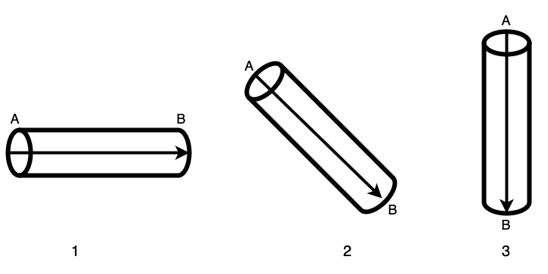
Figure 1 - Voltage and current as water flowing through a pipe
Another set of laws, Kirchhoff’s Laws, quantify how current flows through a circuit and how voltage varies around a loop in a circuit. Based on these for a series connected circuits (e.g. Figure 2), the Ohm’s equation becomes
Vtotal = VLED1 + VLED2 + VLED3
This means that the voltage is shared between all series connected devices.
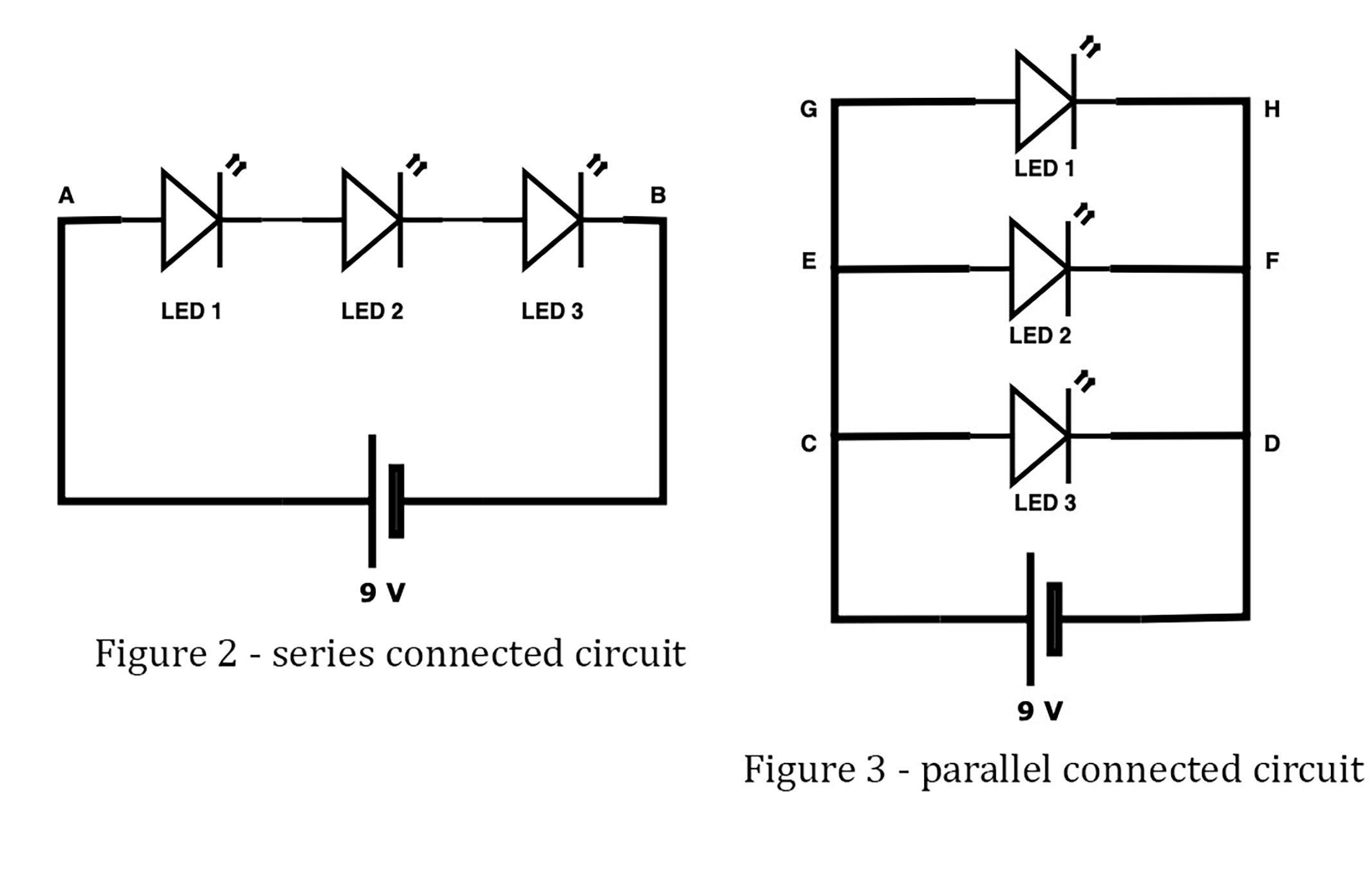
In parallel connected circuits (e.g. Figure 3), following Kirchhoff’s law, the Ohm’s equation becomes:
Vtotal = VLED1 = VLED2 = VLED3
This means the voltage across all parallel connected devices see the same voltage.
In this activity we will look at how to connect series and parallel circuits and measure the voltage across different circuit elements.
Materials
- Energy sources
- A battery pack (5 or 9 volts)
- Potatoes
- Galvanized screws or nails
- Shiny copper pennies (or copper washers)
- Jumper cables
- Alligator clips
- Breadboard
- 6 Light Emitting Diodes (LED)
- Multimeter (optional - check with your school)
Instructions
- Connect the power to the breadboard
- Build a series circuit
- Connect power to the series circuit
- Additional investigation you can try with your series circuit
- Build a parallel circuit
- Connect power to the parallel circuit
- Change the Power Source (see instruction video for more detail)
- Use the alligator clips to clamp on the battery terminals. The standard practice is to use red for the positive terminal and black for the negative (ground) terminal.
- Optional: use the multimeter to read the voltage of the battery - Set the multimeter to DCV (20) and connect the positive probe to the red wire and the negative probe to the black wire.
- Clamp the other ends of the alligator clip to the jumper cables.
- Connect the positive and the negative terminals of the jumper cables to the red and blue power rails of the breadboard. (Now we can draw power from any of the holes in the power rails)
To build the series circuit, connect three LEDs in a series connection (connect the anode (+) of one LED (longer leg) to the cathode (-) of another LED (shorter leg). Standard practice is to start with the positive charge.
- Put the first LED into the board with both legs in the same letter column (e.g. Blue 1 anode (+) in a12, cathode(-) in a13)
- The second LED has to match the number row of the second leg, be the opposite charge and a different letter column (e.g. Blue 2 is anode (+) in c13, cathode (-) in c14)
- Place the third Diode so it is the opposite of the previous diode but in the same number row. (e.g. Blue 3 is anode (+) d14, cathode (-) d15)
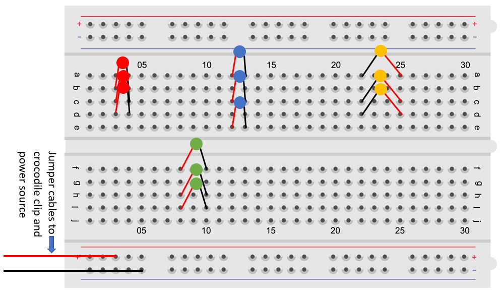
Below are four different sets (red, blue, yellow and green) of three LEDs in a series circuit - where the red leg represents the longer anode (+) leg and black the shorter, cathode (-) leg.
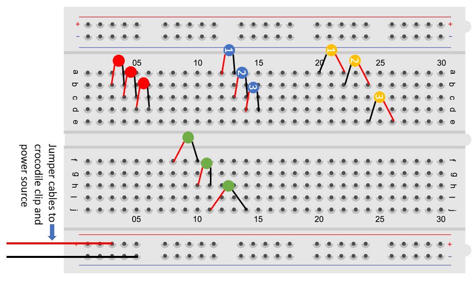
Note - you can start with the cathode (-) on the left as in the yellow LED series circuit example but you are still matching the opposite charge on the next LED.
e.g. Yellow LEDs
LED 1 cathode (-) in a20, anode(+) in a22,
LED 2 cathode (-) in b22, anode (+) in b24
LED 3 cathode (-) in E24, anode(+) in E26
- Connect one jumper cable from the negative power rail to the shorter leg of the last LED (e.g. Blue LED 3 e15) – ALWAYS CONNECT GROUND (negative) FIRST.
- Connect another jumper cable from the positive power rail to the longer leg of the first LED to complete the circuit (e.g. Blue LED 1 - b12).
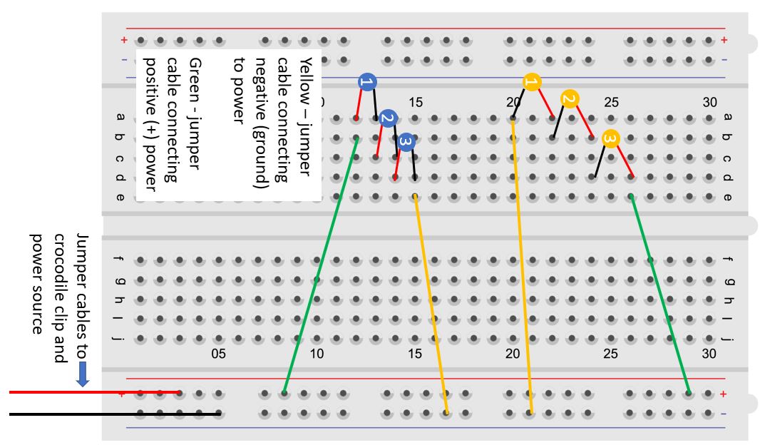
Note - if you start with a cathode on the left (e.g. Yellow LED example) than you connect negative power to the shorter leg of the first LED and positive to the longer leg of the last LED.
- You can increase/decrease the number of LEDs to observe how the brightness changes.
- You can reduce the current flowing through the circuit by adding a resistor. You connect the resistor by replacing it with the jumper cable connecting the positive power rail and the longer leg of the LED (as in the video instructions).
- Try different resistor values to observe the change in brightness of the LEDs, as different resistors will consume different voltages. Here, you can measure the voltage drop by the different resistors by placing the two probes of the multimeter at either end of the resistor and reading the value.
- To build the parallel circuit, connect three LEDs in parallel connection which requires the cathode (-) of all the LEDs to be on the same electrical node (column), similarly for the anodes (+). Hence, connect the first LED probes on any two different rows on the breadboard, numbered 1-30.
- Then connect the other two LED probes in the same manner on any of the five possible column options (a-e) if on the left side of the breadboard or (f-j) if on the right side of the breadboard.
Here are four different sets (red, blue, yellow and green) of three LEDs in parallel - where the red leg represents the longer anode (+) leg and black the shorter, cathode (-) leg.
- To power the parallel circuit, connect the positive and negative power rails to any of the remaining two column options for (+) and (-), as you did with the series connection.

Now observe the brightness of the LEDs and compare this with the series connection.
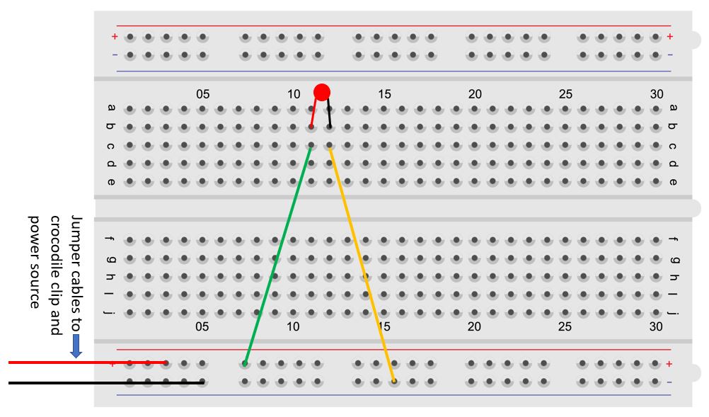
Connect a single LED to power on your breadboard as per the diagram below. Put the LED in first - then connect it to the power .
- Use a table knife to make a slit in the potato. Insert the copper coin (+) into the slit and the galvanized screw (-) into a different part of the potato.
- Connect more potatoes in series to increase voltage – start with two to see if they provide enough power. To do so, connect the anode (+ copper) of one potato to the cathode (- galvanized screw) of another potato using additional alligator clips.
- Optional - You can use a multimeter to measure the voltage of the potato.
- Use a set of alligator clips to connect the copper of an end (terminal) potato to the positive power rails and the galvanized screw of the other end (terminal) potato to the negative power rails. You will notice the LED powered. You will likely need to dim the room lights to see the LED light up.
Note: You can add more potatoes to increase the voltage power to your circuit or you can cut the potatoes into halves and connect the four halves in series to increase the voltage they supply. How many pieces of potato before you can see the LED without dimming the room lights?
Further investigation
- You could try boiling the potatoes to get more potential out of them (meaning it should take less potatoes)
- Substitute the potatoes with other food items like lemons, grapefruit or kiwis.
- Once you get the LED to light up brightly with potatoes what happens if you add a second LED in series? In parallel?
Outreach Newsletter
Sign up to our newsletter and mailing list for updates about Outreach events and activities.